Where are we, and how did we get here? When we last left our hero, the last part for the new memory module was about to come in.
I couldn’t just sit there and admire my handiwork, I HAD to plug it in! The bad news was it didn’t work, the good news was that nothing blew up! OK, what works and what doesn’t? The addresses all seem to work, the read and write pulses seem to work, along with the chip enable.
Output data seemed to have a problem: I had decided to use ‘541 inverting buffers, with 10K ohm pull downs so I could generate small positive pulses, kind of like what the sense amp was looking at. One problem was that when the output was turned off, the level was floating at about 2V! This is not right, according to the spec, the leakage was supposed to be 5 micro-amps, which with a 10K pull down might end up with 0.05V. I swapped out the 10K’s for 470 Ohm resistors, and things looked a bit better.
I had decided, based on playing with some PS sense amplifier modules that maybe I could get away with capacitively coupling to one side of the differential pair that ends up being both ends of the sense wire through the core mat. As I looked at what the sense amps were seeing in the machine, the amps were not liking what I was doing: the levels were going all over the place.
OK, what do I do now? Do I generate the other polarity of signal? Do I shoot myself? The sense amp wants to see something like a wire between the two pins of the inputs. Hmm, we have a small boat load of core modules that we reclaimed from a gold reclaimer. Each one of the back modules has 64 nice Genuine CDC pulse transformers, would they be usable? The secondary is pretty much a wire into which a signal can be induced with the primary.
I extricated about 15 transformers from a board, and kluged them onto my memory. Does that work” No! Well, let’s see: Some of the data bits look like they have reasonable pulses, but some don’t. I found a transformer wire that hadn’t gotten soldered on properly. Eventually I found a couple of transformers wired in one pin off. Now I had pulses on all the pins, but come were positive, and some were negative.
I compared the real core module, and the pulse on the read portion of the cycles was always positive. In my investigation of the PS modules, I had convinced myself that the polarity didn’t matter. Maybe it does? I rewired all the transformers to be the same polarity, which I thought I had done, but reality came up and slapped me in the face saying: No, no!
Now all the bits are positive, except ONE! I must have missed that one somehow. Back upstairs to fix that one. They all have the right kind of pulses, but I get pulses for zeros, and the real one does pulses for ones! Yesterday I convinced myself that I had the data upside down, and changed the data drivers from ‘541’s to ‘540’s, so I guess I was wrong. I Hate it when that happens! After swapping back the ‘541’s, the pulses were all there, and in the right places!
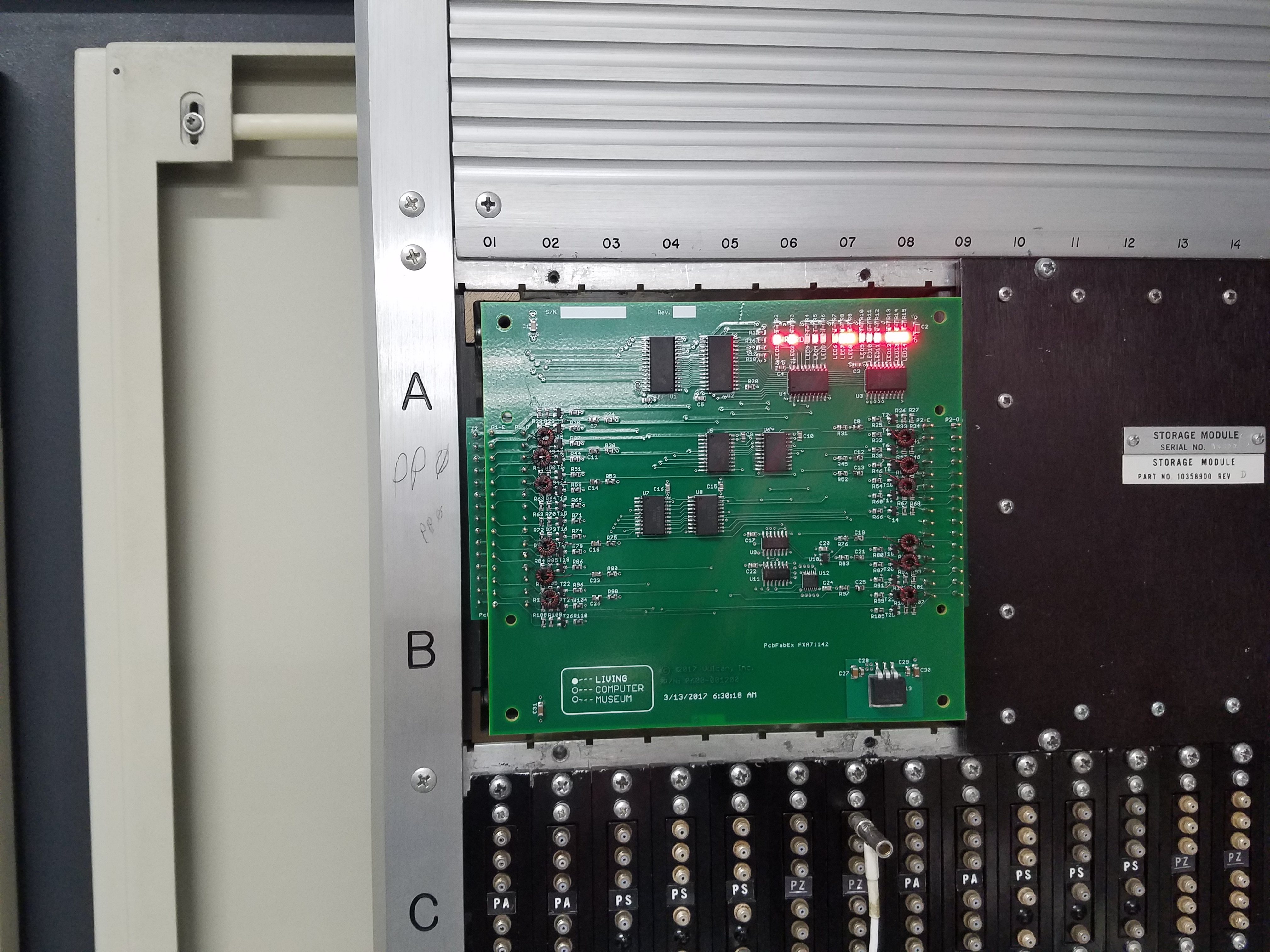
Now SMM came up, and here is a picture of module with PMM, the PP memory test, running:
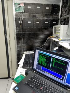
That’s Cool! What about the OS? Here we have the bench, with the laptop which has the console, and you can still see the module in Chassis 1:
Bruce Sherry 3/30/2017 2:56:10 PM